Transform Setup Tab
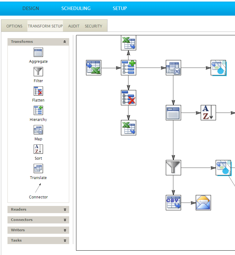
In the Transform Setup Tab you find the graphical design interface. This is the user-friendly template where the integration really starts to take shape. The designer chooses the transform execution sequence, and hence the data-flow, from this screen.
Design > Transform Setup

Transform Palette
Located on the left hand side of the design tab is the transform palette. Nodes from the palette are added to a job by dragging the relevant icon onto the design surface. The palette is segmented into five transform types:
Data Transforms
The transforms modify, manipulate and shape the data.
Readers
The data source or reader transforms.
Connectors
The application connector transforms. Only connectors enabled by the license are listed.
Writers
The writer transforms generate data files/write to raw data formats.
Tasks
Non data-related or workflow transforms, such as Email, FTP or File activities.
Design Surface
The integration is created and maintained on the design surface; it is where the relationships between the transformations are defined.
Setting up a Transform
Drag the transform from the palette onto the surface then double click the icon to open its setup and configuration screen.
The setup screen will open under the following conditions:
- If the transform is either a reader or a task transform.
- If not a read or task, the setup screen will open only when the transform is connected to a configured parent transform.
Connecting Transforms
Transforms are connected through the connector object, located on the Transforms tab.
The connector is an arrow, where the head, indicates the data flow direction.
When connecting transforms, the following rules are applied:
- Each transform can have at most 1 transform as input.
- Reader transforms can only have tasks as input transforms.
- Transforms cannot be connected in such a way that a cycle is created.
- Each transform may have zero or more outputs (as shown below). When a transform has multiple outputs, each of its children transforms receives a copy of the parent nodes’ output.
Using the Connector Object
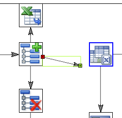
- Select the connector to highlight both the head and tail endpoints.
- Drag the endpoints onto the relevant transforms
- Release when transform becomes highlighted by blue outline.

Deleting Connectors
Connectors may be deleted by selecting with the mouse and pressing the Delete button on the keyboard.
Deleting Transforms
Transforms can be deleted by selecting with the mouse and pressing the Delete button.
If the transform has been Setup, a prompt is displayed asking to confirm the action.
Making Changes to an Integration
Transforms may be inserted, removed and re-ordered at any time. However, there are different requirements for re-ordering configured and non-configured transforms:
Configured Transforms
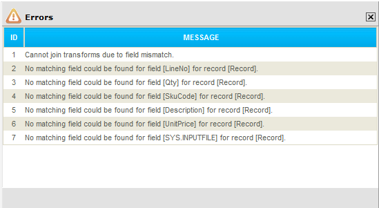
Transforms which are already configured may only be re-ordered if the new transform connection has matching transaction types and data field.
If the connection cannot be made, a prompt is displayed with the reason in the error message.

Non-configured Transforms
Transforms which have not yet been configured can be re-ordered anywhere, as they inherit the transaction types and data fields from their parent transform.